|

These are pictures
taken during the Green Rover's engine, transmission and power steering
conversion. This page represents a quick pictorial overview. I have
written a page describing the engine
swap in detail and one describing the power
steering conversion in detail.
All the fabrication work was done by Timm Cooper, then of Medford
Oregon. The transmission to transfer case adapter was designed
and fabricated by Timm Cooper. I did a lot of wrench turning, the
hydraulic line fabrication and the rewiring.... Oh, and a lot of
parts cleaning.
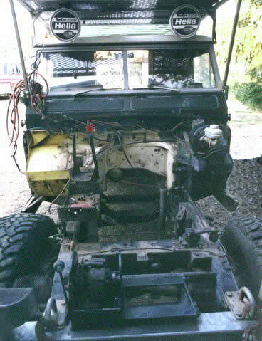
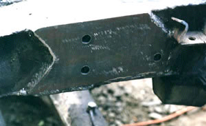
Stripped and ready for the swap
The front body clip, engine and transmission have been removed.
The battery box and engine mounts were removed soon after this picture
was taken. Pay attention to the shape of the bell housing cutout
in the bulkhead. The right half (picture left) of the bell housing
cutout will be removed, moved over 7.6 cm (3 inches) to the right
(picture left) and rewelded. A flat steel patch was welded between
sections. This widened the bell housing cutout in the bulkhead to
allow the engine to be centered in the frame.
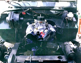
Engine Mounted
Notice the new location of the right side bell housing cutout in
the bulkhead. Moving the side of the cutout 10 cm to the right brought
the edge of the cutout to the edge of the Kodiak heater mounting
flange. The heater and the inside ducting remained in their original
positions. The engine is 2.5cm (1 inch) to the left of being centered
in the frame.
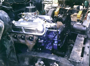
Side of engine
The radiator cross member has been moved forward 2.5cm (1 inch)
to provide clearance between the mechanical fan and the radiator.
The lower tank of the radiator will fit behind the cross member
between the frame rails. The cross member front tabs were shortened
and the mounting holes were redrilled one inch rearward so that
the radiator bulkhead would remain in its stock location. The cross
member seen in front of the radiator cross member is the rear mount
for the Mercury winch.
Note the exhaust manifold. It is the left side exhaust manifold
from an early sixties V8 Ford Falcon. This manifold type was mounted
on both sides. The bottom tilts inwards away from the frame.
Left mounting bracket
The frame mounts were modified and moved forward. Stock Land Rover
engine mounts were used. New steel brackets were fabricated on
the engine side of the Rover mount. Note: In real life the
engine Mounts Timm installed were not up to real life use. A
set of the stronger diesel 2.25 engine mounts never lasteed more
than hale a year and I finally paid another company to build new
rame mounts and install a set of Ford small block mounts
designed for desert racing Broncos.
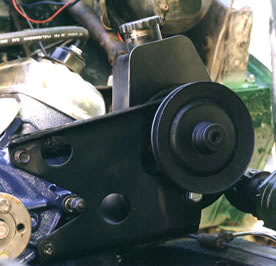
Power steering pump and mount
A Saginaw "canned ham" type steering pump was used because it is
believed to be more reliable than the Ford steering pump. This one
came off a 1980 International Scout. This pump was commonly used
on GM cars. The bracket was modified from an early Ford small block
power steering pump.
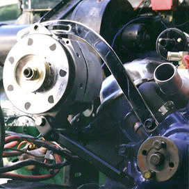
Alternator Bracket
A high amp Delco alternator was used since The Green Rover was
already wired for a Delco. The Alternator was mounted as high as
possible on the engine to keep it above water while wading. The
top mounting bracket is a GM V8 alternator top bracket. The lower
bracket was fabricated from scratch.
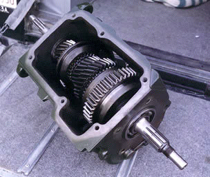
Borg Warner T-18 transmission
This T-18 gearbox has the rear output shaft reworked to fit the
Land Rover output gear and transfer case. This is a key part of
Timm Cooper's T-18 to LR transfer case conversion. The large gear
is the Granny first gear. With the stock series 4.7 ring and pinion
the first gear provides a 70:1 low range rock crawling ratio. The
T-18 transmission is available in both close ratio and with a granny
first. It does not have syncro in first gear. The T-19 is the all
syncro version of this gearbox. The T-18 and 19 gearboxes were widely
used and highly regarded as a strong trouble free light truck transmission.
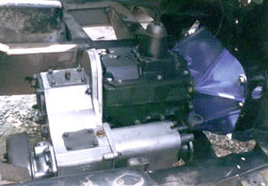
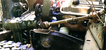
Mounted in place
Here you can see the reworked T-18 gearbox sandwiched between a
stock Ford bell housing and the stock Land Rover transfer case.
There is a thin metal adapter plate between the gearbox and the
transfer case allowing them to be bolted together.
The Transfer case is in it's stock front to rear location but was
moved to the right when the engine was centered in the frame. The
steel transfer case mounts attached to the transfer case were modified
for the difference in location. The stock LR rubber mounts and frame
mounts remained unmodified. There is a bell crank that mounts inside
the right frame rail that pulls the lever on the emergency brake.
This bell crank had to be modified for the new lateral location
of the emergency brake.
Clutch slave cylinder
The stock Series II clutch slave cylinder was used. A mounting
bracket was fabricated out of the original mounting bracket. The
Ford throw out bearing release lever was modified to fit the stock
Land Rover slave cylinder rod.
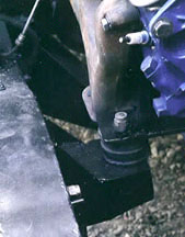
Power steering
A Saginaw power steering box from a 1980 International Scout was
used.
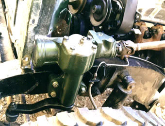
Power steering box mounted into place
The power steering box is mounted on the outside of the frame rail.
Note the front of the box is right behind the radiator bulkhead.
The box is placed so that the bottom is forward of the axle housing
and the suspension stops. The stock mounting tab for the front brake
was cut off for clearance. There is an unused hole at the bottom
of the tab that is the correct size for mounting the flex hose connection.
It has the advantage of providing additional slack in the brake
line to handle increased articulation.
The Scout pitman arm was shortened to work on the Rover. The stock
length provides approximately 2-1/2 turns lock to lock. The arm
was shortened and a new hole was drilled at 8-1/2 inches then reamed
out to fit the Land Rover tie rod end. This provides just under
4 turns lock to lock. This is just slightly faster than D110 power
steering.
A new larger diameter drag link was fabricated using the ends of
the original link. This provided an increase in arm strength.
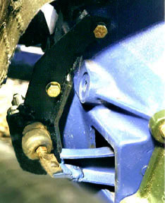
Mounting plate for steering box
The mounting plate is made of 3/8ths inch thick steel. Grade 8
nuts were welded to the back. Clearance holes were drilled in the
frame then the plate was welded to the frame. A 3/8ths inch steel
strap was welded to the frame bottom below the side bracket for
additional strength.
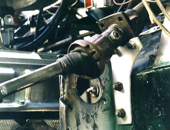
Steering column bracket
The steering column was unbolted from the box and reused. The worm
gear was cut off the bottom of the Land Rover steering shaft and
the end of a GM steering column was welded to the bottom of the
Rover shaft. When I asked about strength of the weld I was shown
where the original stock Land Rover steering shaft was composed
of three steel parts welded together from the factory.
A special bushing was machined to support the bottom of the shaft
in the bottom of the Land Rover steering column. A mount was fabricated
out of a steel plate to mount the lower column to the bulkhead.
The top of the flange on the old steering box mount was cut off
for clearance.
Collapsible GM steering shaft
A collapsible GM steering shaft with a 'U' joint at each end connects
the steering box to the steering column.
Return to page top
|