|


DRAFT Page still in process
In the beginning Land Rovers had a single circuit non-boosted brake system. There was a single can style reservoir holding fluid for both the brake system and the clutch system. Over the years ideas of what constitutes a safe brake system changed. Late in Series IIA production, Land Rover started converting to power boosted brakes then to dual brake systems. The years the changeovers occurred were different from market to market. As people got used to the newer systems their expectations have changed as well as their sense of what is safe and what is not. More and more people feel a strong desire to convert their Series II and early IIA Land Rovers to a power assisted dual brake system. This web page attempts to guide you through the various common upgrade paths. For those who want to go a step farther I have a page providing an overview of available disc brake conversions that you can add to the power dual brake system.
Common Series Land Rover power brake conversions:
Series III brake tower and servo |
Easiest conversion. Easiest to find parts for in North America. only minor cutting to SII & early SIIA bulkheads |
Series III brake tower and Santana servo unit |
Easiest conversion. Correct Santana Servo sold by Heystee Automotive Provides easier braking than SIII servo conversion with no extra cuts for clearance. |
Early Ninety/One Ten brake tower and type 50 servo unit |
Almost easiest conversion if outside North America. Harder to find parts for if in North America. Provides same breaking as Santana servo unit. Not extra clearance cuts. Possible bonnet stiffener mod needed for pedestal clearance depending on fit. |
Pre-1990 Ninety/One Ten brake tower and type 80 servo unit |
Tight fit in Series requiring additional cutouts to SIII wing panel, deluxe bonnet with side flange modifications. Cuts may be visible if using standard bonnet. Harder to find parts for in North America. Pre-1990 pedestal should be matched with pre 1990 type 80 servo unit. Provides easier braking with more modern truck feel. |
Post-1990 Defender Power brake components |
The brake tower and Servo mounting changed when the petrol Land Rover four cylinder engine was discontinued. For petrol Series Land Rover conversion look for a non-ABS tower and servo and make sure the pedal assembly and servo are for the same year. Fit problems are to those of pre 1990 type 80 servo conversion. Provides easier braking with more modern truck feel. |
The best way to perform a Series Land Rover brake system upgrade is to decide which type of servo you want and purchase a brake pedal assembly, servo unit and master brake cylinder for that were all sold together for the same truck. It is all pre engineered to work together and it minimizes unanticipated gotchas.
An overview of the Land Rover power brake conversion process:
- Fitting a new brake pedal
- Power brake pedals are hinged differently from the early non boosted style and have the return springs in different locations. This will require some modifications to the bulkhead opening for the pedestal. The mounting bolt location remains the same. The power brake pedestal mounting is the same for all years.
- Modifying or replacing the wing panel
- Either cutting the rear inside of the wing top for clearance or swapping to a late Series IIA or Series III inner wing panel to create clearance for the brake servo unit and new master cylinder location. The late Series IIA and Series III wing top profile will fit the Series brake servos the type 50 servo and the Santana servo with no modifications. There may need to be minor expansion for master cylinder clearance. The type 80 servo will require additional clearance cuts which may be visible at the edge of the bonnet.
- Replacing the master clutch cylinder with a Series III style master brake cylinder that has its own reservoir.
-
- Relocating the brake light switch wiring
- The brake like switch gets moved to the brake tower when you switch to the dual brake circuit. It is at the top of the SIII pedestal and at the back of the Defender style pedestal.
- Replumb the hydraulic lines for both the clutch and brake system
Step 1 - Choosing the Servo unit
The servo unit you choose to use defines which brake pedal assembly would be best to use. The following combinations will be the easiest conversions with the least amount of body cutting: Stock Land Rover Series III style, or stock Land Rover Series III style with Santana servo unit or early 1980's type 50 brake servo from an early NINETY or ONE TEN.
Series Land Rovers and Santana servos connect to the brake pedal linkage the same way and fit the Series brake pedestal. The NINETY and ONE TEN servos connect to the brake linkage in different way. Which is why you need to choose which Servo you want to use then choose the pedal assembly that is compatible with the servo rod. Also there was a pedestal and servo unit mounting width change made for the 1990 model year which is why if using a type 80 servo you should match the pedal box to the servo unit.
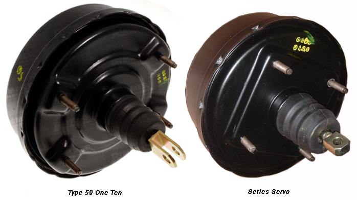
The Series Servo has a six inch diameter diaphragm which provides a boost of approximately 2:1 over a non assisted pedal. The Type 50 has an eight inch diaphragm that provides an even greater power boost. I have been told that you can squeeze the fork on the early defender rod and make it fit into the Series pedal. I have not seen or done this.
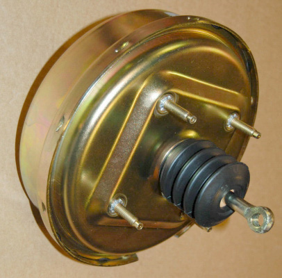
8 inch Servo unit sold by Heystee automotive
|
Heystee
Automotive offers a larger 8" diaphragm servo as an alternative to the standard 6"diaphragm unit found on the late SIIA and SIII Land Rovers.
The larger diameter allows more servo boost with lower pedal pressure than the Series servo unit. Heystee Automotive has done the work of identifying and offering the correct Santana servo unit that properly fits the Series Land Rover brake pedestal and brake pedal linkage. The Series III Land Rover master cylinder also mounts directly onto this servo. No alterations are required to for this upgrade.
This unit is the same diameter as the early ONE TEN and NINETY type 50 units. The only difference is that the Series pedal needs a eye fitting where the NIETY/ONE TEN pedals need a fork fitting. |
The advantage of going to the Santana servo unit or the Type 50 servo unit is that it adds braking power and fits into the the Series III wing cut out for the power brakes. The type 80 servo unit has fit issues that need to be addressed. The type 80 servo has a ten inch diaphragm that produces even greater boost but it requires use of the taller deluxe bonnet and additional cutting in the wing top for clearance.
The easy solution for a brake servo is to just get a late Series IIA / SIII brake tower and servo, STC1816, and just bolt everything together. This is the most common servo in North America and you know everything will fit it you have a SIII wing cut out. For Americans and Canadians this is the easiest and generally least expensive upgrade to obtain.
The next step up would be to couple a common Series III brake pedestal. with a Santana servo unit. This upgrade is provides greater boost using the Series III wing cut out and the common SIII pedal assembly. It would also be a good boost increase for Series Land Rovers that came factory equipped with power brakes. This will give you approximately the same boost as converting to a Type 50 servo while allowing you to use a Series III pedestal.
The Type 80 provides the greatest level of boost that I am currently aware of. You should couple the type 80 servo with the same year brake box for ease of assembly. You will need additional cuts and a deluxe bonnet to make it fit.
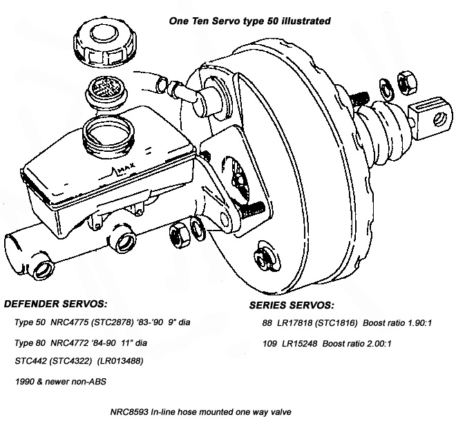
There are at least three power brake pedestals that can fit a Series Land Rover and it is important to match the servo unit with the pedestal. The Series IIA & III pedestal. will only fit the Series and Santana servo units. The Defender pedestal used before 1990 will only fit the type 50 and type 80 servo units. The pedestal used in the 1990's defenders will only fit the later non-ABS servo units. When using Defender pedestals be sure to measure the servo to pedestal mounting distances to help assure fit.
LR part number |
Fits |
Servo mounting spacing |
Master brake mounting |
STC1816 |
Series IIA & Series III |
3-9/16 X 3-9/16" |
3-3/16" (80 mm) |
STC2878 |
90-110 type 50 1990 & earlier |
3-9/16 X 5-9/16" |
3-3/16" |
NRC4772 |
90-110 type 80 1990 & earlier |
3-9/16 X 5-9/16" |
3-3/16" |
STC4322 |
90/110 Non ABS 1991 on |
|
|
Measurements provided by Trevor at the Rovahfarm
Step 2 - The brake pedestal
"All 90/110/130/127 Defender brake pedal towers from inception up to and including Td5 models fit the same six-hole opening as the US late IIa/SIII pedal tower. The bolt pattern is exactly the same. Clutch pedals are interchangeable too, allowing one to fit the latest Defender clutch pedal with an over-center spring assist to an earlier Series vehicle. Be advised the 90/110 Defender stuff is all metric so you will need new bolts. (The six-bolt cover for the clutch tower comes unthreaded so you can use the original self-tappers)" From David Bobeck. The mounting of the servo was changed with the 1990 model year.
The pedal to servo rod linkage is different between Series Land Rover and NINETY/ONE TEN. You want to use a Series pedestal with a Series or Santana servo unit, a NINETY/ONE TEN pre 1990 brake pedestal with a type 50 servo unit and match the type 80 servo unit with the same year pedestal unit to make sure the pedestal to Servo mounting is correct. I've been told that the type 50 servo rod ends can be squeezed together so that they can work with Series pedestal linkage, but I have not seen that combination so can not verify this.
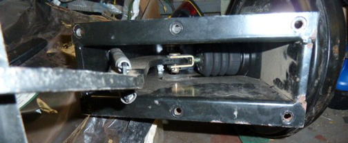
Underside of a NINETY/ONE TEN brake pedestal showing the pedal to servo connection.
Photo courtesy of
William Leacock
The pedal on a power brake pedestal is hinged on the opposite
end of the tower as the pedal on a non-boosted pedestal. This means
you needed to elongate the rectangular opening in the bulkhead for the pedal. The
mounting bolt holes stayed in the same location. The power brake pedestal uses dual side return
springs so you will need to make the pedal slot a little wider to keep the
springs from rubbing on the bulkhead. Once you are sure of the fit,
you can smear RTV along the base of the pedestal and bolt it into
place.
NINETY/ONE TEN brake pedal assembly with type 80 servo mounted.
Photo courtesy of
William Leacock
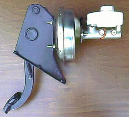
Series brake pedal assembly with Santana servo and Series 88 master brake cylinder
Photo from Heystee Automotive
Step 3 - Fitting the pedestal to the bulkhead
The early single circuit and later power brake pedal assemblies are hinged at different places on the brake tower so the hole in the bulkhead needs to be elongated when converting from the early single circuit brake system to the later dual brake system. There is a gasket between the pedal tower and the bulkhead.� The cut in the bulkhead for the old assembly is at the top half of the gasket.� Mark the inside of the lower half of the gasket and continue the bulkhead hole down along the edges of the mark.� The SIII and later Defender towers have 2 return springs, one on each side which will rub against the bulkhead.� You will need to file the lower hole sides just a little wider to clear the springs. The mounting holes are in the same location for all the brake towers.� Be sure to seal the connection between the bulkhead and brake tower when you mount the tower.� Otherwise there will be rain water flowing down onto your foot. The Series gasket is no longer available. If the gasket needs to be replaced order one for a newer Defender.
Step 4 - Vacuum line
You need to connect a vacuum line between the intake manifold and the inlet of the servo unit. The easy way to do this is to source a late Series IIA/Series III intake manifold that is alreadydrilled and tapped for a vacuum line connection. You could probably get away with drilling and tapping (pipe thread) the earlier intake manifold. There is a one way valve fitted between the intake manifold and servo unit. The connector that comes off the SIII type intake manifold has the valve inside. If you don't have one you can make due of a generic hose mounted one from your local auto parts store.
Step 5 - The master brake cylinder
Whichever servo unit you choose it is best to go with a Defender master brake cylinder if you are also installing disc brakes or with a Series master cylinder if staying with all drum brakes.
This advice comes from Paul Heystee of Heystee
Automotive . Paul recommends using using a
Defender master brake cylinder with a disc brake conversion. The
1993 D110 master brake cylinder available in North America
would be a good choice for a Series Land Rover that has front
disc brakes and rear drum brakes.
"The reason for changing to an early Defender master cylinder when converting to disc brakes
is because these designed specially for discs/drums set-up. Master
cylinders designed for drum brakes have a so called "remainder
pressure" that keeps the shoes close to the drums. Using this
type of MC with a disc/drum or disc/disc set-up will push the pistons
constant to the disc wearing out the pads quickly ("in no
time"). Also the disc brake set-up requires less volume
to work but this is not an issue because the LR pedal has already
a long travel and a short travel is welcome. The tandem set-up
will allow to keep pushing fluid to the rear although the front
is saturated."
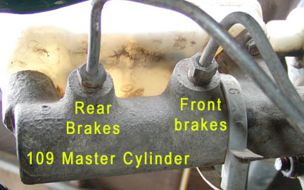
If you are keeping drum brakes just use the appropriate 88 or 109 dual master brake cylinder with whatever servo unit you chose. The 109 has dual front wheel cylinders on each side.
The 88 has a single wheel cylinder on each wheel. The master
cylinder supplying fluid to 109 front brakes needs to be capable
of pumping more fluid than the 88 master cylinder pumps.
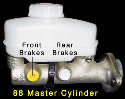
Here is how to tell an 88 Master cylinder from a 109 master cylinder
by looking at their profiles:
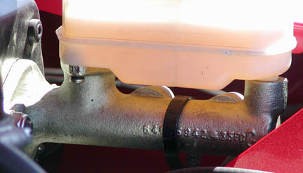
This is a new 88 master brake cylinder
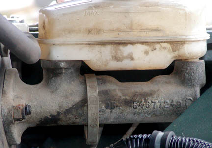
This is a not so new 109 master brake cylinder
The 109 master cylinder is connected so that the tubing for the
front brakes is connected to the larger diameter cylinder, located
closest to the booster. The tubing for the rear brakes is connected
to the front most cylinder.
This is opposite
the connections on an 88. The 88 master cylinder
has the front of the cylinder going to the front brakes.
The fitting for the rear brake line is
larger diameter than the fitting for the front brake line.
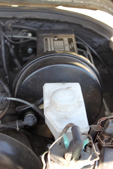
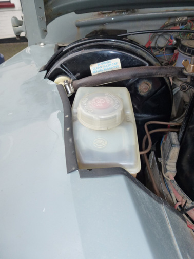
Step 6 - The master clutch cylinder and pedestal.
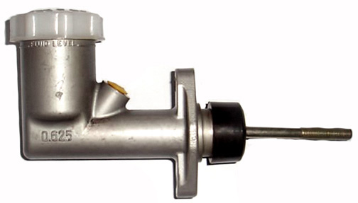
Land Rover Series III master clutch cylinder
|
You can get by with an early master clutch cylinder and the reservoir can with one outlet blocked. But without the reservoir mounting plate it would be awkward. The best solution is to convert to a series III Land Rover master clutch cylinder that
has its own built in fluid reservoir. The clutch pedestal is unchanged from a single brake line system to a dual brake line system so all you need to do is bolt the SIII master clutch cylinder to you old clutch pedal assembly. The Series III master clutch cylinder is the same for both the 88 and 109.
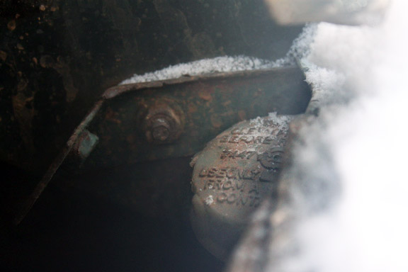
The cap is half covered by the SIII wing top but still accessible for filling |
Step 7 - Clearance on the wing
For wing clearance on a SII or early SIIA you can either replace your inner wing assembly with a SIII inner wing panel or cut out your existing early wing panel. A stock SIII inner wing panel will fit a series servo, a Santana servo (As sold by Heystee Automotive) or type 50 NINTY/ONE TEN servo. A deluxe bonnet and an additional wing top clearance cut would be needed to fit a type 80 servo.
A SIII inner wing panel is basically a bolt on fit to an earlier truck. You will need to drill out a couple spot welds and replace them with pop rivets if you are fitting an early wing front panel to a SIII inner wing assembly.
If you plan to stay with your earlier non-power brake wing, parts of the wing need to be cut away to make space
for the new brake booster and the forward extended master brake cylinder. You will want to make a tracing of the SIII cut out to use as a cutting guide.
With the bonnet closed place the point of an erasable marker about 45 degrees inward under the edge of the bonnet and draw a line along the top of the wing from the bulkhead to about halfway along the wing top. This line marks the farthest outward that your cut should ever go. Raise the bonnet. There is a flange on the underside
of the wing top for mounting the splash shield. Your cut should
end before reaching the flange so you can reinstall the splash
shield. Mark the location of the mounting flange on the top of the wing. Your final cut will be inside these marks. Lay your tracing of the model III wing top cut out on the wing to be cut. Adjust it so that the cut will reach the inner edges of your lines but do not cross them. Mark the cut line on the wing top. You will notice that you will be cutting off two of the three wing top to bulkhead mounting bolt locations. The SIII wing only uses a single outer rear wing top mounting bolt. Cut out the rear inside of the wing top along your drawn line. File any sharp edges or uneven edges. You may have to file the cut for a little for additional clearance when you mount the wing. If you are converting to a type 80 servo system you will need to cut a notch for the larger servo diameter. Aftermarket master brake cylinders use a non-stock plastic reservoir that sticks out a little farther than the stock plastic reservoir. You may need to file a little of a SIII or your cut out wing top for additional clearance with the aftermarket master cylinder.
There is a mounting bracket on the bulkhead that supports the rear
of the wing. You will need to cut part of the top of this bracket off
to provide access to the series III clutch reservoir. You can cut
the top part of the bracket off to match the wing cut. This will leave you with one bolt mounting hole left on the bracket which is the same as on a Series III. After trimming the bulkhead flange a little over half of the cylinder reservoir cap will be exposed.
Alternately you can make a minimum cut onto the top of a SII or SIIA wing top cutting just the minimum needed to clear the servo and master cylinder. If you make this minimal cut you will need to cut off the back of the wing top for access to the master clutch cylinder. The front of the cut panel will need to be reattached to the wing top with a piano hinge. The cut out part of the wing top will be anchored by the piano hinge and the top rear mounting bolts. The wing top will be a lot more fragile after this modification. Cutting the early wing top to match the cut on the SIII wing top is the stronger solution and you will not have a visible cut for the piano hinge.
NOTE for type 80 into Series conversion:
The type 80 requires the use of a deluxe bonnet for extra vertical clearance and either cutting or folding over the edge of the bonnet flange where it goes by the servo unit.
Photos courtesy of
William Leacock
|
 |
Below are some pictures of pre 1990 NINETY/ONE TEN brake systems and some Series power brake conversions.
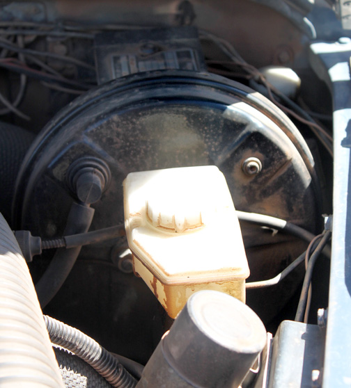
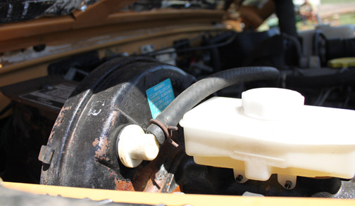
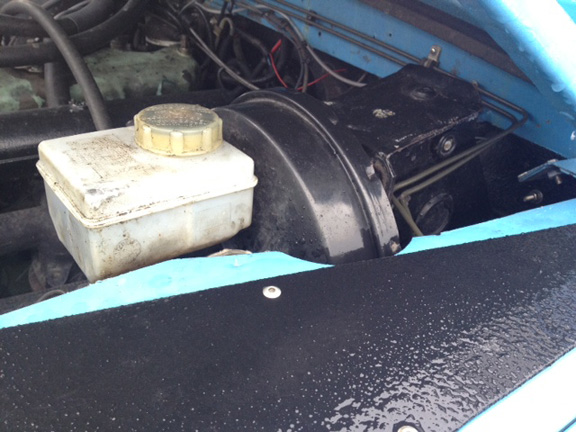
The first three pictures are from 1983 ONE TENs showing a type 50 Servo unit The type 50 is the same size as the Santana unit described above.
The overall shape of a Land Rover type 50 servo is very similar to that of a Series Land Rover servo unit though the type 50 servo is larger in diameter.
Shown at wing top level. The type fifty does not protrude much above wing level.
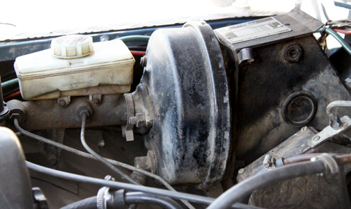
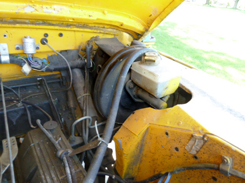
The next 3 pictures show a Land Rover type 80 servo in later 1980's ONE TENs
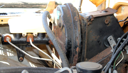
Notice that the diameter is greater than the type 50 and the front to rear distance is quite a bit less.
There was a snorkel in the way of a wing level picture but you can see that the Land Rover type 80 servo units is a lot taller than the others, requiring a deluxe bonnet.
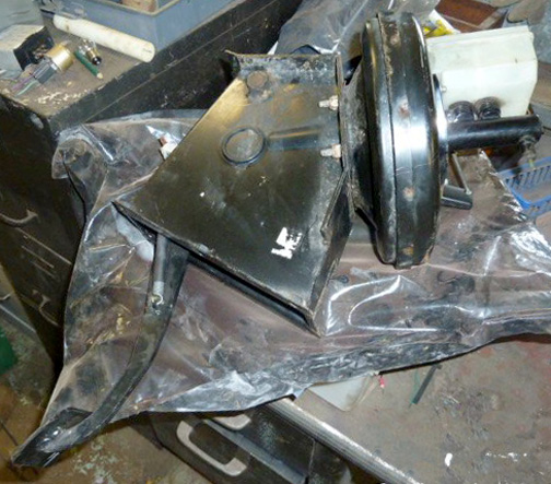
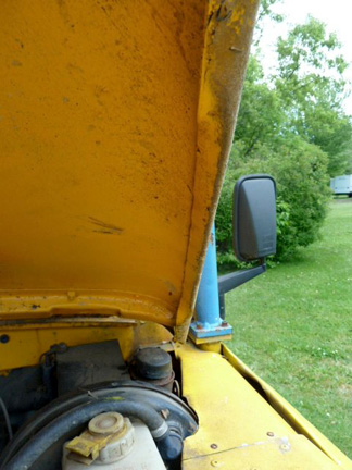
The 2 pictures below show a Land Rover type 80 system installed in a Series Land Rover.
ABOVE AND BELOW:
Type 80 system with a Series III wing. Photos courtesy of
William Leacock
This is an early Series IIA with pre-1990 D110 brake tower, post 1990 non-ABS servo unit & master brake cylinder, and deluxe bonnet. So it can be done but it took modifications to get the late servo to fit the early Defender tower and additional cuts in the wing top to clear the larger servo. An earlier type 80 servo unit would have been a bolt on fit to the tower. A type 50 would have also been a bolt on fit but without the extra clearance notch.
Photo courtesy of Micah Gustafson
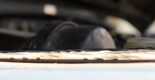
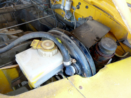
Below Type 80 installation on a RHD 1961 SWB series 2A with standard bonnet
Courtesy of David Gilbertson
 |
From David:
"My Land Rover is a RHD, 1961 SWB series 2a. It originally had the CB type master cylinder (which I changed for a CV type as good quality replacements are readily available at a sensible price). When I fitted the TI disc brake conversion I was not happy with the amount of effort that I needed to apply to the brake pedal.
"I fitted the Series 3 pedal box, servo and single line Girling master cylinder (this had been an option I believe on later SWB 2a's and standard on S3's until a dual line master cylinder was introduced. This involved elongating the slot in the bulkhead in order to accommodate the new pedal box as the pedal is suspended differently. It all worked pretty well but I still found I needed quite a bit of effort on the pedal - and as a single line system seemed to me that until the rears were 'on' then the discs did not operate to their full potential. So I figured that I would try to replicate the same installation as Land Rover fitted to the late 1980's Defender 90 which had discs front and 10" drums rear.
"I had to bend one of the top corners of the pedal box to allow the bonnet reinforcement to clear. Servo fitted perfectly but of course there is the issue with the bonnet! I found that in my case (razor edge) I just had to ease the lip and it pretty much cleared ( it is very close though - but no matter!). The master cylinder fitted in OK too albeit with a big chunk of inner wing having to be removed ( I have made up a longer mudguard/shield to prevent ingress of the water/dirt from being thrown up from the wheel and into the new gap).
" I modified the brake lines to a dual system - also I now have metric fittings on the master cylinder end of the pipes and imperial at the ends which connect to the existing system. The only major 'visible' externally is that I have had to cut some pieces for the top of the front wing to clear the servo - not much ...but visible - I guess this is where the deluxe bonnet would win as it it slightly wider down its length and it would probably cover this. However, as I do not want to fit a deluxe bonnet I will live with this.
"So, the result. Much less pedal effort to operate the brakes. They feel better balanced and although I have never owned a 90 I have had several Discoverys..and the brakes are now on par with how they behaved. Am I happy - you bet. " |
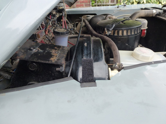
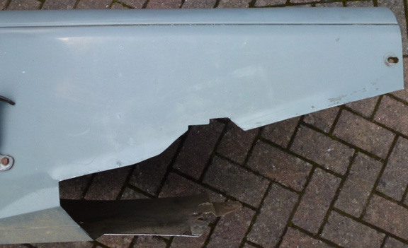
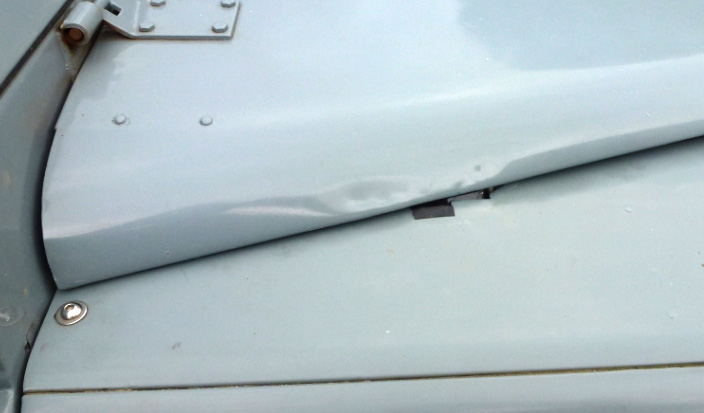
The bottom side flange needs to be bent up to fit the Land Rover type 80 servo unit. Though Dave allowed minimal clearance between the servo unit and wing panel you can still see a little of the cutout. Standard bonnet.
Step 7 - Brake light Switch
The brake light switch on the non- servo brake system is located on a five way connector down on the frame. This connector is eliminated when you plumb a dual brake system so you need to convert to a mechanical brake light switch located on the brake tower and reroute the brake switch wires. The brake light switch on the Series power brake tower is located on the top behind the servo. The brake like switch on a NINETY/ONE TEN tower is located on the back of the tower.
Safety Considerations - Please read
A car's brakes can save your life and the life of others if they
are in proper working condition. I recommend that any modifications
to a braking system be performed by experienced brake professionals
and that any design used be tested thoroughly as a complete system.
If you decide to modify your Land Rover's brake system please be
very careful. Any mistakes can lead to brake failure. I do not in
any way recommend that you make modifications to your Land Rover's
brake system, nor do I claim that this story is accurate or complete.
Please read the copyright notice attached to this web site and accessible
from a button at the bottom of this page.
If you do decide to make any modifications be very sure that you
use the correct fittings and the correct tubing flares, properly
made.
American brake fittings and British brake fittings are different
and incompatible. They will interconnect but are not safe to use.
The British male fitting has a long snout ahead of the threads.
The American one does not.
When you screw an American male fitting into a British female fitting,
the flare will not seat.
When you screw a British male fitting into an American female fitting,
the flare will seat with only one or two threads holding the parts
together.
Also be aware that Land Rover started converting to metric in
1981 so bake parts intended for newer Land Rovers and some aftermarket
parts may require metric fittings.
Dual master cylinders designed for the 88 will not work properly
on a 109 brake system. The 109's front brakes have two cylinders
per side while the 88's has only one. The 88 master cylinder will
not push enough fluid to properly work the 109's brakes.
Always use new brake fittings and the proper brake fluid. For British
brake systems this is DOT4 or DOT5.
Steel brake lines should be clamped to a surface. Unsupported lengths
of rigid tubing vibrate and eventually will get fatigue cracks at
the fitting junction.
There are probably more safety concerns that I have not mentioned.
Please just be careful when working on your own brakes.
Return to page top
|