|

Mercury Winch
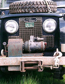
The Green Rover came with a Mercury winch that was made in Vancouver
Canada. The Mercury Winch company has fallen into obscurity. I
have never seen another winch like mine so have decided to document
it in the hopes of finding other people with one & finding out
more about the winch. I don't know what its rating
would be but this winch has never been stalled on a single line
pull.
I've seen pictures of a later Mercury winch called the M10 (rated
at 10,000 lbs pull). It has a more production like winch frame
and what appears to be a smaller motor (This appears to be very
similar to an old Waren winch). The clutch for the later M10 was
patented in 1976 by H. R. Therkelsen (United States Patent 3985047 pdf file).
The Mercury Winch manufacturing company Ltd was still doing busines in
Vancouver BC during the mid 1970's
There
was a Mercury Winch International, Inc. in Bellevue, Washington
in 1978. I suspect that it was the same or successor company. Anyone
have any additional information? It's a 35ish year old product
that seems to have been lost to winch history.
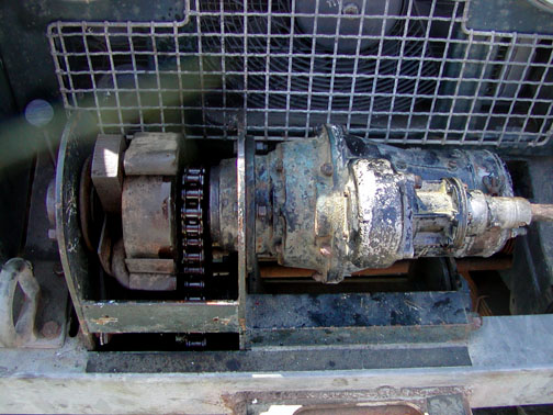
This
is what the winch looks like with the top cover removed. It
is chain drive snd you can se the clutch/brake which is operted
by the leaver on the left side of the winch.
The winch frame is mase from plates of sheet steel and steel angle
stock. It us a heavy rugged frame.
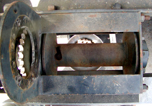
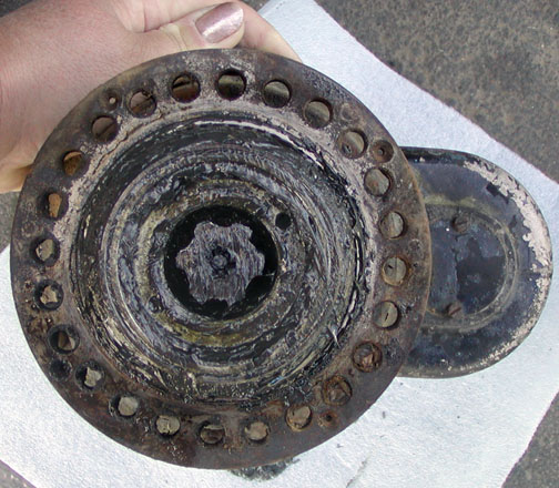
Lookng down at the drum you can see the cable attachment method.
You weld a washer to the end of the cable and slip it into the
hole on the drum. The drum appears to be designed for 100
feet of 3/8ths cable but will hold 125 feet of 3/8ths cable.
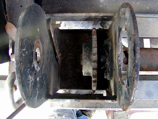
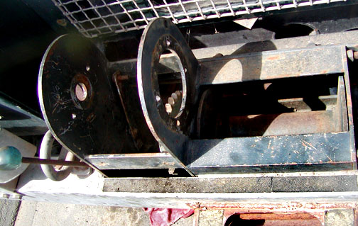
Looking down into the normally enclosed gear/chain./clutch area
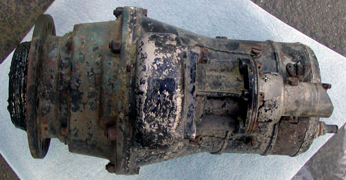
Winch motor from the top. Notice that all the bolts are tie
wired and the motor is sealed.
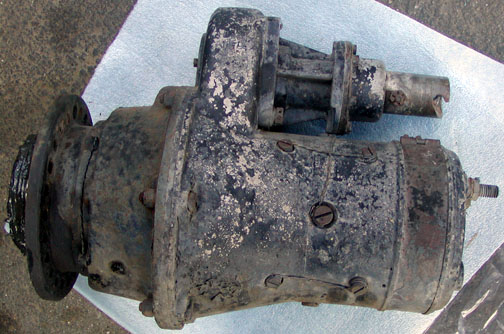
Side view of the winch motor. And yes that is a manual crank input
allowing the winch to be operated by hand.
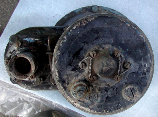
This is the back of the winch motor. Note that there is only a
single electrical contact. The motor uses the case as ground
so only turns in a single direction. You need to manually
pull out the cable and the motor can only pull cable in.
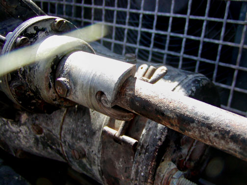
Here is the hand crank input sleave with a Series Land Rover hand
crank attached.
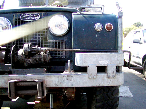
This picture shows the Series Land Rover hand crank in place. Crank
it and turn the winch!
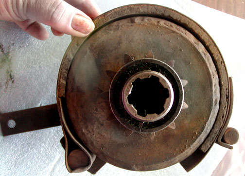
The front of the winch motor with the front dust cover removed.
The ring of mounting holes allows you to position the manual
crank adapter to any angle you wish.
Looking at the clutch.brake assembly. The motor output shaft
fits into the demale gear which sits at the end of a shaft that
goes through the assembly. Around the female gear is
the clutch/brake drum and drive gear for the chain drive. The
drum and drive gear are a single part that is not connected to
anything else. You can see the outer brake shoe and friction
material. There is a smaller inner shoe. When the shoes
clamp to the drum the motor turns the drum which drives the winch,
pulling the cable in. When
the shoes are loose, the drum is free to move on its own and you
can manually pull out the the winch cable. The leaver in
the back activates the brake shoes.
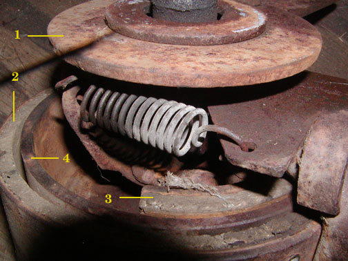
Its hard to get a picture of the inside of the brake/clutch assembly.
1. some sort of friction
lever that activates the brake/clutch. Turn
the leaver one direction and the brake sets when the motor
shaft turns. Turn the leaver in the other direction
and the brake/clutch disengages. I can not see how
it works so near as I can tell its magic of some kind. |
2. Outer brake shoe and friction material |
3. Inner brake shoe and friction material |
4. brake/clutch drum |
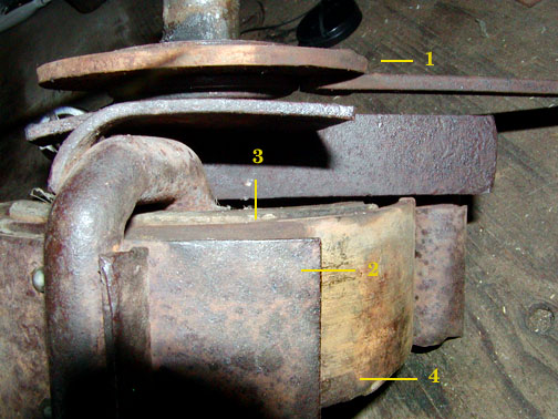
The centre driven shaft goes through this assembly. The steel
block is secured to the driven shaft by a woodrif key and turns
with the driven shaft. The outer shoe is attached to this and
turns whenever the motor turns. You can see the top of
a U shaped rod that attaches to both shoes. When the rod
is tited in one direction, the shoes are loose. When the
U shaped rod is tilted in the other direction both shoes clamp
together by the force of the turning motor. Somehow that
clutch (item # 1) sets the angle the U rod.
Thats about all I know about this Mercury Winch. If
you know anything more I would apriciate an email.
Return to page top
|