The British Standards institution (BSI) creates and maintains standards for British industries, one of which is colour coding automotive wire insulation based upon the use of the wire. This is a great help to those of us maintaining our own British cars allowing us to glance at a wire and know what it is being used for. This standard is periodically updated as vehicles become more complex with more colour combinations used and in some cases the uses are changed for a colour combination. Colour code tables for BS-AU7a (1983 revision) and newer are commonly available on the net. What I am trying to document is colour uses for 1960's and earlier British cars. I may miss some colours & some uses. Series III Land Rovers have a more complicated wiring system using additional coloured wires, but most of the uses remain the same as called out in this page. Additionally, replacement wire harness manufacturers have to pick a version of the standard for building their looms and the version they use may be newer than what your vehicle was originally built to so some insulation colours might not match what your vehicle had from the factory.
I have added some newer standard codes for accessories that
might be added to a series Land Rover, such as rear fog lamps,
a rear window wiper and washer, driving lamps, radio and electric
fan. In general solid colours go from the power source to
a switch and a stripped wire goes from the switch to the switched
electrical component. If you have a newer vehicle with
more a more complicated electrical system here is a link to a chart
that covers newer vehicles as outlines in a newer
version of the colour code.
Please note that Land Rovers built to military specifications use
a different wire colour code.
| Black |
All ground connections |
| Black/ Purple |
Temperature switch to warning light |
| Black/ Green |
Relay to radiator fan motor, windscreen wiper switch to single speed wiper motor. |
| Black/ Light green |
Brake switch |
| Black/ Light green |
Brake differential pressure valve to warning
light |
| Black/Orange |
Radiator fan motor to thermal switch |
| Black/red |
From 3 prong flasher unit to flasher light |
| Black/white |
Flasher unit light to ground |
| Blue |
Headlamp connections |
| Blue |
Headlamp switch to dimmer switch |
| Blue White |
Headlight high beams, Dimmer switch to long-range driving light switch |
| Blue/ White |
High beam dimmer switch to high beam indicator
lamp |
| Blue/ light green |
Windscreen wiper switch to motor |
| Blue/ Red |
Headlight low beams |
| Blue/ Yellow |
Long range driving lamp switch to lamp |
| Brown |
Main feed from the battery. No switches or fuses |
| Brown/Yellow |
GEN 'D' to volt. Regulator 'D'. Ignition warning light |
| Brown/ Blue |
power feed to headlamp switch and voltage regulator to ignition switch |
| Brown/ White |
Ammeter to main alternator terminal, or voltage regulator |
| Brown/ Yellow |
Alternator to 'no charge' warning light |
| Brown/ Purple |
Alternator Regulator feed |
| Brown/ Green |
Fuse to horn (No relay), Generator 'F' to voltage regulator 'F' |
| Brown/ Lt. Green |
Windscreen wiper motor to switch |
| Brown/ Black |
Horn to horn button (no relay) |
| Green |
Ignition switch controlled
wiring for auxiliary devices, switched 12V to individual wiper motors, to brake lite switch, flashers, etc |
| Green/ Black |
Fuel gauge to fuel tank unit (Light green/black for vehicles with voltage stabilizer) |
| Green/ Orange |
fuel low level warning light to sensor on fuel tank |
| Green/ Slate |
Heater motor to fast position on 2 speed heater swtch |
| Green/ Blue |
Water temperature gauge to temperature sender
unit (Light green/black for vehicles with voltage stabilizer) |
| Green/ Blue |
low fuel warning light to fuel sender unit. |
| Green/ Brown |
Switch to reverse lamp |
| Green/ Red |
Direction indicator switch to left-hand flasher
lamps |
| Green/ Purple |
Stop lamp switch to stop lamps |
| Green/ White |
Direction indicator switch to right hand flasher
lamps |
| Green/ Yellow |
Heater switch to slow speed on heater motor
or for single speed motor |
| Green/ Yellow |
oil pressure light to oil pressure switch |
| Green/ Gray |
Heater switch to high speed on heater motor |
| Light green |
voltage stabilizer to instruments on LRs fitted with voltage stabilizer |
| Light green |
choke cable mechanical switch to carburetter heater element (Solex optional fitment) |
| Light green/ Black |
Windscreen washer switch to washer motor |
| Light green/ Blue |
Flasher switch to left-hand flasher warning
light |
| Light green/ Yellow |
Flasher switch to right-hand flasher warning
light |
| Light green/ Brown |
Flasher switch to flasher unit 'L' |
| Light green/ Purple |
Flasher unit 'F' to flasher warning light |
| Light green/ Orange |
Rear window washer switch to motor |
| Light green/ Red |
fuel mixture light to fuel mixture thermostat switch (vech. with carb heater) |
| Orange |
Wiper circuit (single motor
wiper system) |
| Orange/ Black |
Wiper switch to to motor parking |
| Orange/ Blue |
wiper switch to low speed on motor |
| Orange/ Green |
Wiper switch to high speed on motor |
| Orange/ Yellow |
Rear wiper switch to rear wiper motor |
| Orange/ Light green |
switch to rear window motor parking |
| Purple |
Accessories fed direct from battery via
fuse (Always live) |
| Purple/ Brown |
Horn fuse to horn relay when horn is fused
separately |
| Purple/ Red |
Switches to map light, under bonnet light,
glove box light and boot lamp when fed direct from battery
fuse |
| Red |
Tail lights, instrument lights, parking
lights and side markers |
| Red/ Yellow |
Fog light switch to fog light or front fog
light fuse to fog lights |
| Red/ Blue |
Front fog light fuse to fog light switch |
| Red/ Brown |
Rear fog guard switch to lamps |
| Red Orange |
Power to rear fog guard lamp fuse |
| Red/ White |
Fuse to instrument lamp switch, Instrument
panel lamps |
| White |
Ignition circuit, no additional switches,
not fused |
| White |
Power to coil, fuse to cold running light (vech. w/o carb heater) |
| White |
Power to electric fuel pump |
| White/ Black |
Ignition coil to distributor |
| White/ Black |
Distributor side of coil to tach impulse sensor |
| White/ Black |
mechanical choke cable mounted switch to cold running thermostat switch (1960's vech. w/o carb heater) |
| White/ yellow |
mechanical switch on choke cable to thermostat switch( in 1970's, white black earlier) |
| White/ Brown |
Oil pressure switch to warning light or gauge |
| White/ Blue |
cold runing light to mechanical switch on choke cable (vech. w/o carb heater) (light blue in 1970's) |
| White/ Pink |
Ignition switch to radio fuse |
| White/ Red |
Ignition switch or starter switch to starter
solenoid |
| Yellow |
Generator connections wired through the
ignition switch and electric overdrive wiring |
| Yellow |
Dynamo 'D' to voltage regulator 'D', Voltage regulator 'D' to gen. light on instrument panel |
| Yellow/ Green |
Dynamo 'F' to control box 'F' Alternator field
'F' to control box 'F' |
| Yellow/ brown
yellow/Blue
Yellow/Rd
Yellow/purple
Yellow/Gren |
Overdrive related wiring |
Note that this is an abreviated list showing colours most
likely encountered on a Series Land Rover and circuits a Series
Land Rover owner is likely to add to their vehcle. Here is
a link to a colour
code chart that covers newer vehicles with more electronics.
Flasher units have to be connected to the turn signal switch circuit in a certain way and are marked in a way that is far from obvious. So here are the markings and where they go for a 3 prong flasher unit. The same code works for the 2 pin flasher as well.
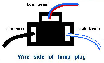
Sometimes you might purchase a replacement headlamp socket from a company that provides pig tail leads that do not follow ther British standard and you need to figure out which circuit each lead needs to be connected to.